Electrical & controls
How to Measure and Identify a Replacement Proximity Sensor
A proximity sensor can fit the same bracket as the original and still send the wrong signal to the controller. Record the physical fit and the electrical specifications together.
Where to measure
Reference drawings. Verify dimensions on your part or the manufacturer’s drawing.
Threaded sensor body
Sensing face and target
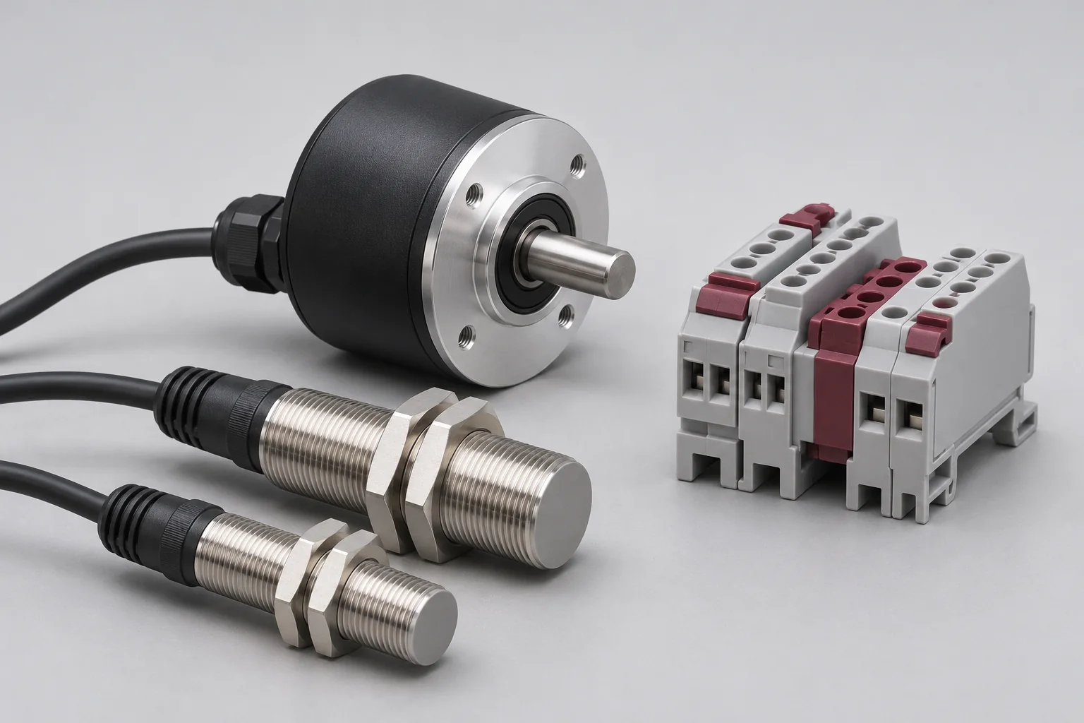
Measure the housing and bracket
For a cylindrical sensor, record the thread diameter and pitch, the usable threaded length, and how much room there is behind the bracket for the cable or connector. For a rectangular sensor, record body dimensions and mounting hole center distances. Include a photo showing how the sensing face sits in the bracket.
Identify the target and sensing distance
Record what the sensor detects and the approximate gap between the sensing face and the target in service. Use the datasheet to identify the rated sensing distance and whether the sensor requires flush or non-flush mounting. The observed gap is useful context for selecting a replacement.
Match the output and connection
Record supply voltage, PNP or NPN output where applicable, and normally open or normally closed operation. Include the connector size, pin count, pinout or cable length from the documentation. For an encoder or drive, use the full catalog number and its wiring and feedback specifications.
Manufacturer reference: Pepperl+Fuchs industrial sensor selection guide